Computer Nerd Kev |
Home|About|Projects|Links |
Projects > VecAdapt > Tech |
VecAdapt Technical Information |
The Vectrex itself uses a very simple controller circuit, which can bee seen in this schematic from the Vectrex service manual:
Nothing more than switches and potentiometers, with a ± 5VDC supply.
The Sega Mega Drive / Genesis controller is somewhat more complicated. It uses a 74157 2:1 multiplexer IC to switch signals so that two inputs can be read off each pin (like the Vectrex, the signals go low when the buttons are pressed). A "Select" signal determines which signal is sent depending on whether it is high or low. The later six button controllers complicate things a bit, but they're backwards compatibility means that the new buttons can also be ignored without change.
My source for a detailed look at the Mega Drive / Genesis controller is "Sega Six Button Controller Hardware Info" by Charles Rosenberg (local mirror). It's a good read (yes, pity me).
No, that's not an abstract impression of a spider playing the harp, it's the VecAdapt schematic in all its glory.
Note: Recommended value for R14 is now 6K8.
First thing to note is that I've gone the boring route with the button inputs and used the matching 74139 Demultiplexer IC for the signals coming from the 74157 Multiplexer in the Sega controller (hey, why not combat 80s technology with 80s technology?) . With SW1 at GND, this Splits out the button signals from input pins 6 and 9 to A1, B1 and A2, B2. However with SW1 at Vcc, the signals instead go to C1, D1 and C2, D2.
Deciding which signal should be sent along each wire is the NE555 Timer IC which switches the "Select" signal at around 120Hz. This uses an oscillator design which does not use pin 7 and requires only one external resistor in order to oscillate. It means that the output frequency may vary a bit, but that doesn't matter in this design, so we can save some power and the extra resistor by using this configuration.
Following the 74139's outputs, we soon come to the 7409 Quad AND Gate with Open Collector Outputs (we'll get to the outputs in a tick). The confusing arrangement of inputs to these AND gates ensures that with the switch SW1 at Vcc, the button assignment reverses for the "Button Swap" function.
Now the capacitors on the button outputs come into play. You see each time the 555 switches the Select signal, the deselected output from the 74139 goes high, so with a button pressed, the corresponding 74139 output becomes a 120Hz square wave and causes the Vectrex to register the button repeatedly being pressed instead of held down. The 22uF capacitors keep the signal close enough to GND during the positive pulse so that the Vectrex registers the button press correctly. The Open Collector outputs of the 7409 IC don't bring their outputs to Vcc when the signal goes high, instead just disconnecting them from GND. The button outputs are brought high by internal pull-up resistors in the AY3-8912 IC (IC208) which reads the button signals inside the Vectrex, so the capacitors can recharge relatively slowly (but still fast enough to prevent rapid manual button presses being filtered out) from these pull-up resistors inside the Vectrex, and the 120Hz positive pulses aren't passed on to the Vectrex.
SW2 disconnects GND from C7, so that it no longer acts as a capacitor filtering the Button Four output. This passes the 120Hz square wave to the Vectrex instead of a steady low signal, therefore enabling the Auto-Fire function.
In case you're thinking that all the electrolytic caps in this thing means it will need re-capping after a while, as many Vectrex consoles do now, I used 100V rated Nippon Chemicon SME capacitors in the production VecAdapts for sale. So they're far over-speced and a good brand, I'd say they're a good bet at standing the test of time.
As the Vectrex controller's analogue joysick works on ± 5VDC, we need the low signal on either Up/Down or Left/Right to switch the corresponding polarity to the X and Y outputs, which is done using discrete PNP transistors. The positive switching simply works by pulling the base of the positive switching transistor (either Q3 or Q5) to GND, therefore turning it on. The negative side (Q4 or Q6) uses a 5V1 Zener Diode that conducts to the transistor base when the input is high (there is ~10V between the Zener's cathode, and its annode which is held at -5V by R3/R10), when the input is at GND the voltage isn't high enough for the Zener to conduct and the transistor Base is pulled to -5V by R3/R10, turning it on.
Because the Left and Right inputs are switched to GND by the controller when Select is low, Q1 and Q2 turn on when Select goes low and keep Q3 and Q4 turned off by holding their Bases high.
The two capacitors on the X output (pin 5) are arranged for bipolar use and together with R13, filter the noise that the Vectrex generates on its controller inputs. R14 also supresses noise on the Y Axis (pin 6).
And there we are, that's pretty much the lot. C9, C10, C11 & C12 simply filter the supply voltage from the Vectrex to eliminate noise. Other than that, there's nothing more to mention. I hope that satisfied your curiosity.
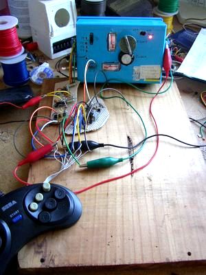
I first built a "Vectrex Controller I/O Emulator" to avoid having to test the unproven circuit on my precious machine.
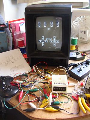
Then moved on to the real deal. It turns out the Vectrex generates quite a lot of noise on the controller inputs, which messed me up a bit as it wasn't in my "Emulator".