
Computer Nerd Kev |
Home|About|Projects|Links |
Projects > Pseudo-Switch |
The Pseudo-Switch |
The Pseudo-Switch is a fully electronic alternative to mechanical slide and rotary switches. It allows full electronic control, while retaining a simple manual interface with a push button and LEDs to indicate position. Single boards can be joined together to expand the number of switch positions, and the output can be disconnected entirely with activation of the "Inhibit" mode, allowing multiplexing of multiple switches on one signal line. Analogue and digital AC or DC signals can be switched with ease.
DP4T (double pole, four position) Pseudo-Switches are now available for sale from my online store, OmberTech. Or from Tindie.
| Supply Voltage | 3.0 - 5.5V DC |
|---|---|
| Supply Current | <50mA |
| Max. Switch Input Voltage | +5.0V, -4.5V(3V Vcc) +5.5V, -5.5V(5V Vcc) |
| Max. Switch Current | 20mA |
| Switch ON Resistance | <120 - 500 Ohms |
| Switching Time | 2 Microseconds |
| Switching Configuration | Break Before Make |
| Dimensions | 43x42mm |
This is an example C function to advance the position of the switch a specified number of places, optionally resetting it beforehand to ensure the final position is correct regardless of whether the built-in push button has been pressed to advance the position manually. It also sets the state of the Inhibit function.
Fill in the missing definitions to suit your microcontroller configuration.
// Example Configuration function for Pseudo-Switch Analogue Switch Board from OmberTech
// 2018 OmberTech. No warranty. May be used for any purpose.

#define MICROSECOND			// Approximate number of execution cycles required for CPU to complete "for" loop in microsleep function

// Microcontroller outputs connected to Pseudo-Switch:
#define	CLOCK
#define	RESET
#define	INHIBIT

// Delay for specified number of microseconds (alternatively use hardware timer):
void microsleep (unsigned int microseconds)
{
        unsigned long i;
	while (microseconds--)
		for ( i = 0 ; i < MICROSECOND ; i++ );
}


// Modify Pseudo-Switch configuration:
void pseudosw ( unsigned int clk,	// Number of switch positions to be advanced
		char rst,			// If 1, reset switch position to "A" before advancing position
		char inh )			// If 1, enable Inhibit mode (no switch contacts selected). If 0, disable Inhibit mode.
{
	INHIBIT = inh;
	if (rst)
		{
			RESET = 1;
			RESET = 0;
			microsleep (5); // Ensure Reset has been disabled
		}

	for ( ; clk > 0 ; clk-- )
		{
			CLOCK = 1;
			CLOCK = 0;
		}
	microsleep (5); // Wait for switching time
}
Using the above function, this would move the switch to the fourth position (D):
pseudosw (3,1,0);While this would advance it two positions ahead of its previous position (the switch will loop back around if it reaches the last position):
pseudosw (2,0,0);Finally, this turns on the Inhibit function of the Pseudo-Switch without changing its set position:
pseudosw (0,0,1);INHIBIT = 1;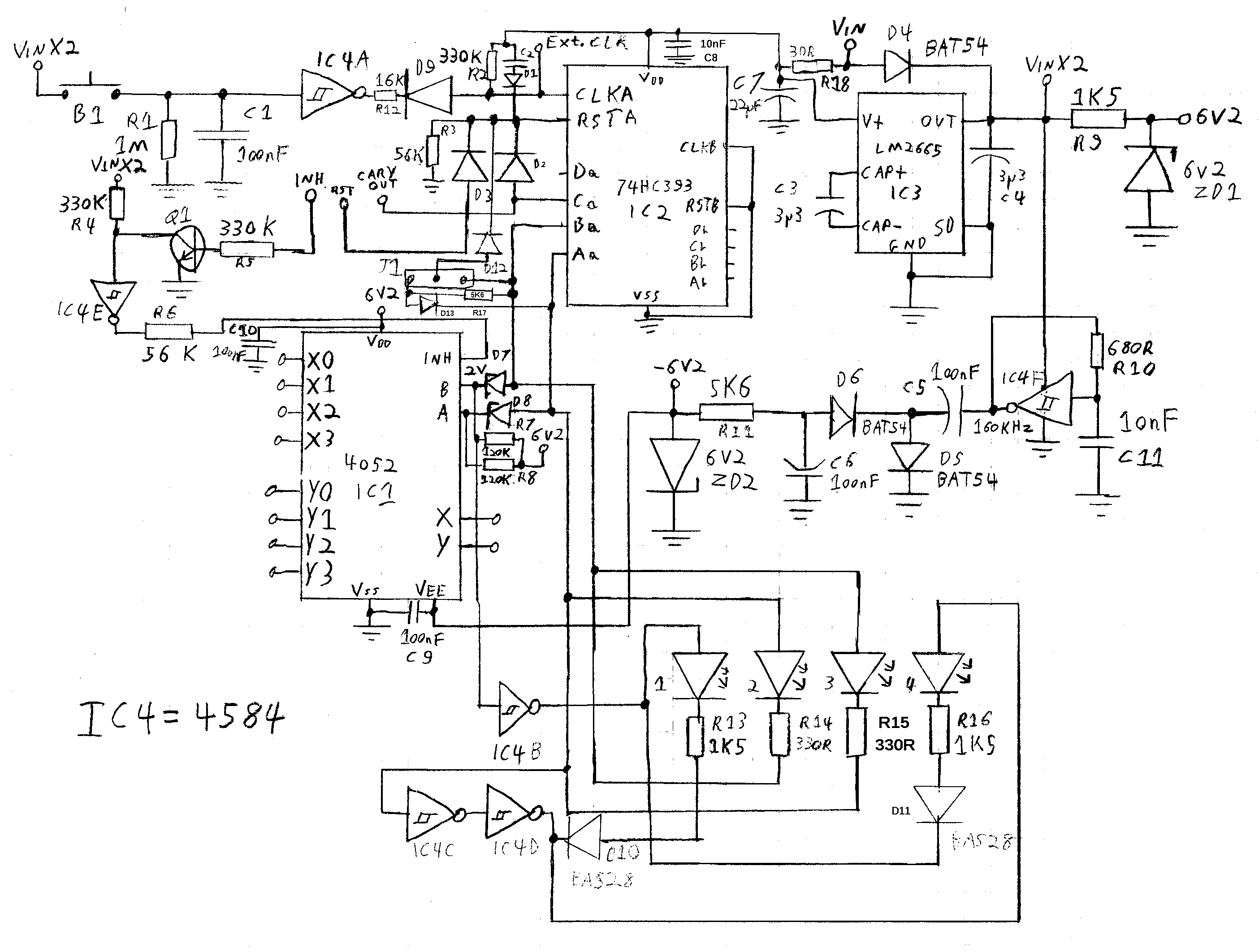
The Pseudo-Switch DP4T is based around the 4052 analogue switch IC. It is controlled by a 74HC393 binary counter which is advanced either by the built-in push button, or by an external Clock signal. It is reset according the to setting of the position selection jumper, or by an external input.
In order to switch negative voltages, and voltages higher than the supply, two capacitive voltage converters are built in to the Pseudo-Switch. These generate an internal ±6.2V supply for the analogue switch IC. This allows it to switch AC signals and other bidirectional currents, just like a mechanical switch.
A full circuit description is available in the User Manual, which can be viewed or downloaded above.