Don't scream, it was just ice cream.
Computer Nerd Kev |
Home|About|Projects|Links |
Projects > IC Testers > DSA |
DSA IC Tester Build Notes |
Project's Webpage (Wayback Machine)
The website for this project has been down for many months now, so I've changed the link to the Wayback Machine archive. Unfortunately it doesn't seem to have archived any of the downloads there, so here are the ones that I had saved. The images are missing, but all that's required for building and using the IC tester is there.
Before identifying the full range of IC tester options made open to the average constructor through the paper or protocoled transfer of information from many masters of the electronic art. Before even the aid of kind, humble, internet servants arranging the many such works on one easily referenced webpage. I found myself looking upon but a tiny selection of DIY IC Tester projects, found with nothing more than some breif web search queries, concerned with a determination to bring one to an actuality upon my barren workbench.
This design appealed to me particularly due to the number of ICs in the provided library (138), along with the test library editor included in the software, which I hoped would slightly ease the tedious job of adding tests. Along with that, it is a sound hardware design, able to adequately test a large majority of logic ICs likely to be encountered.

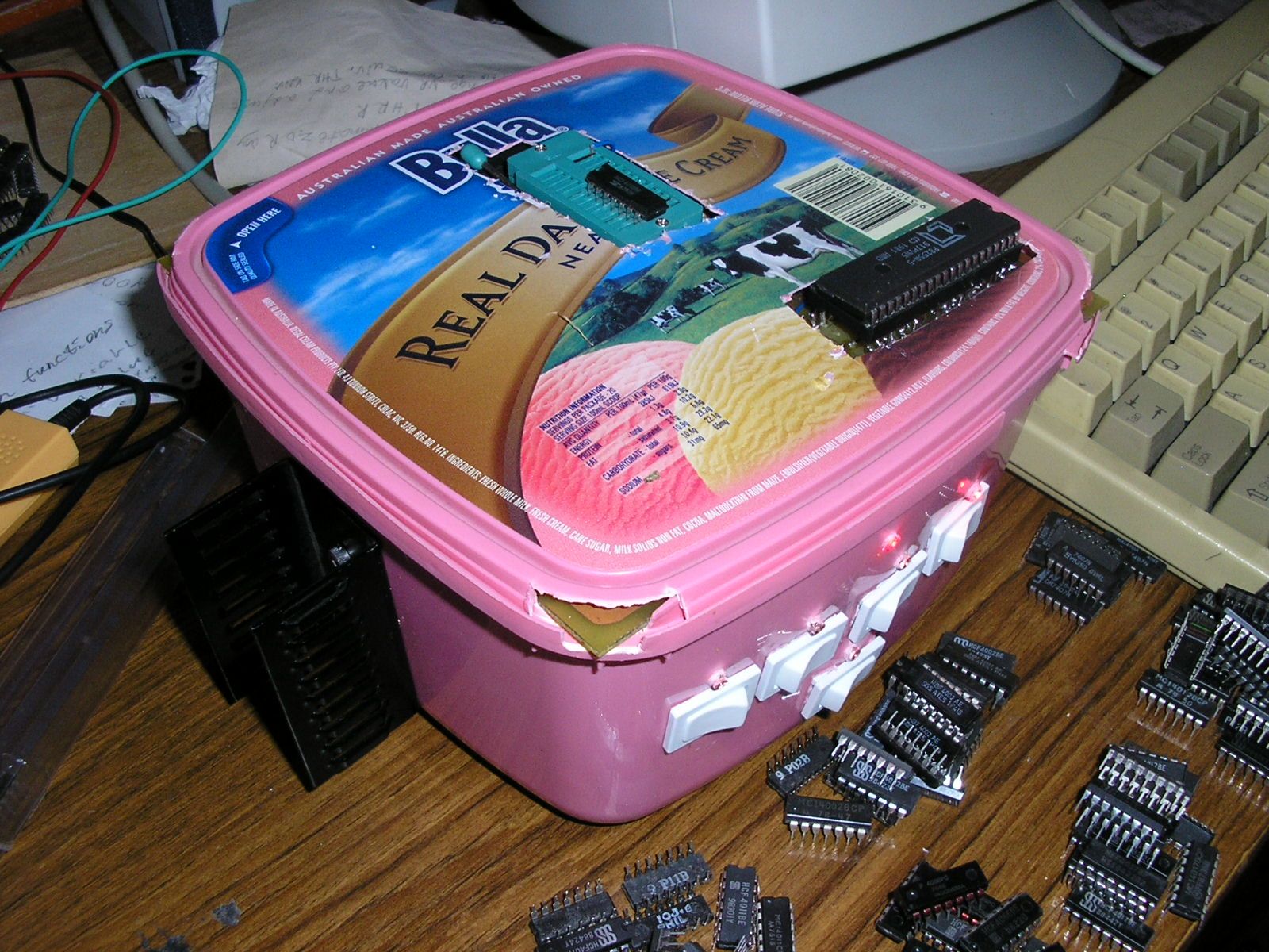
The design allows for relays to control the power connections to ICs of varying sizes, however as I had none that suited the circuit board layout, I decided to connect the coil power lines to LEDs mounted above manual switches on the front of the case. This does introduce the risk of leaving one switch on by accident and the output of a test IC being accidentally shorted during the test. However it can make the device much cheaper (at least if, like me, you've made some well timed investments in bulk packs of switches), and I enjoy a degree of manual control.
On the subject of supply to the power pins of ICs, I have made the observation that some CMOS ICs are sufficiently powered via the 4K7 pull-up resistor on the tester's pin connection, to actually perform their full logic functions without the direct connections to Vcc and GND being made. This is not the most reliable testing method, some ICs might perform in this situation when they are actually damaged and will fail when the full supply current is applied in use. More likely is the effect I have observed that good ICs from one manufacturer may fail the test while others of a different make, but the same model, pass. As such any IC that fails the test should not be pronounced dead until an examination under proper supply voltage conditions has been performed (hook up the power patch leads). In light of these limitations, a more respectable use of this effect than pure (but from my perspective understandable) lazyness in the face of some uncooperative patch leads, would be with the IC identification feature of the software. If the unknown IC is suspected to be CMOS, this trait of the tester might avoid the need to know the power pin locations if they are not in the standard locations.
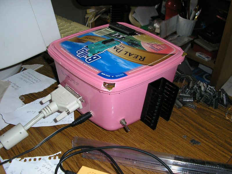
As far as I could tell, the design did not specify the power requirements of the tester. The only voltage required is 5VDC, and by tallying up the power consumption of the major components (substituting the current to the relay coils for 8mA to my LEDs) I concluded that a 500mA supply should be sufficient. An unregulated 9V DC plugpack was used to deliver the power externally, then a 7805 regulator with a medium sized 6° C/W heatsink was built into the side of the case as shown. A 2200uF filter capacitor was used to combat any input ripple due to the resistance of the power lead, along with a normal 100nF ceramic capacitor to take up the fight against high frequency noise.
The many under-IC connections on the top of the circuit board proved exceedingly difficult to get right, and were a major source of problems. Additional wire connections were made directly between pins when under-IC solder joints were determined to have failed. The fact that my eye was often a little off when drilling the holes in the PCB didn't help matters. A professionally manufactured board with CNC drilled plated through holes becomes quite attractive in this context. In this regard, note that the design files are only provided in Protel format, so either you, or your PCB manufacturer, will have to be able to read this format in order to have boards professionally made (I'm always open to donations of any extras left over, by the way :) ).
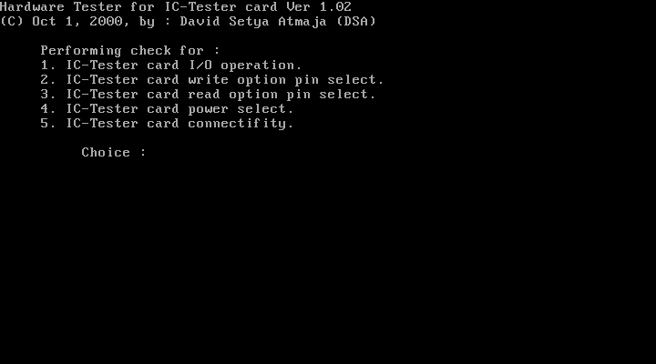
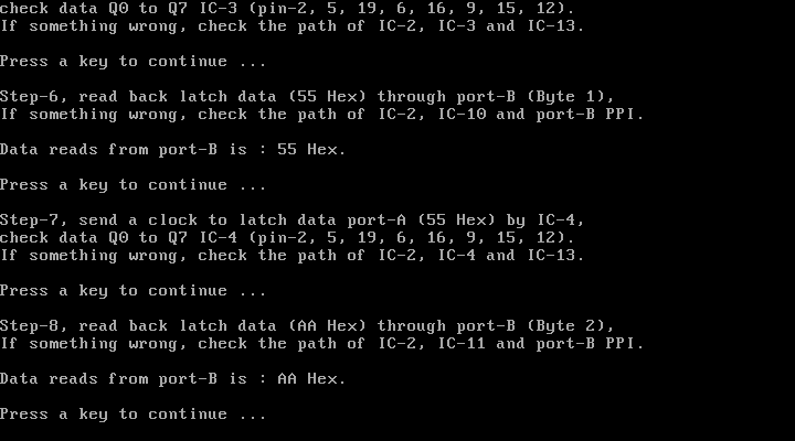
I intended to use a socket for the 8255 IC, but found the misalignment of the holes I'd drilled made it impossible to bend the 40 socket pins in a way that they would all slide into the PCB. I eventually gave up and soldered the chip in directly like the rest. Naturally I later came to the slow realisation that it was faulty. This realisation was made difficult by the fact that it failed in a very particular way - the inputs and outputs all responded to the PC when running the (very handy, if not entirely user friendly) HWTEST.EXE program by the project's author, but not in the ways intended. After studying the full datasheet (the one downloadable from the author's website is certainly better than some others) I finally concluded that my 8255 was failing to properly change between its internal operating modes and was therefore the definite cause of my troubles. Many suppliers are quite expensive with this obsolete IC, but I was able to buy a pair for just a few dollars from a Chinese seller on Aliexpress. With a socket creatively soldered onto the cut pins of the old chip, one of these NOS 8255s finally brought some new life to the tester, and with a few much simpler wiring errors corrected, it was finally in operation.
The under-IC pin connections have proved a common failure point over time but hopefully I'll weed out all the dodgy ones eventually, patching in wire connections as required. The female pin header connector I used to connect the front panel LEDs and switches proved horribly unreliable, so I later replaced it with a ribbon cable and the associated type of plug and socket. The wiring hassle of these connections might mean that I'd have been better off with the relays, but then I couldn't find ones with a pinout to suit the PCB layout anyway...
The component layout image in one PDF on the author's website shows the buffer ICs around the test socket as 7405s rather than the 7407s mentioned elsewhere. 7405 corresponds to open-collector inverter ICs, whilst 7407s are open-collector buffers, both using the same pinout. An email to the author resolved my concern over which chips to solder down to my PCB. 7407 ICs are the intended ingredients, as stated on the parts list on the web page.
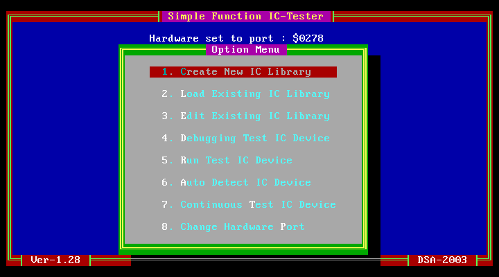
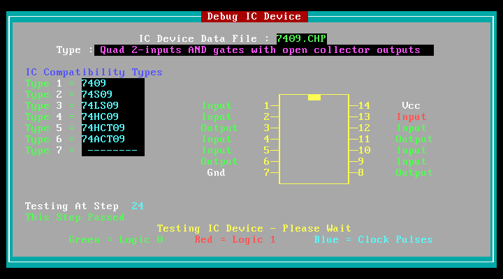
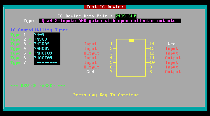
The software for the DSA tester generally works well enough, although the odd bug becomes evident when attempting less usual sequences of actions. The standard test procedure is easily initiated with just a few key presses, first to load the test data for your IC, then to initiate the test, which runs almost instantly (on my Pentium 1), returning with a blinking pass/fail result announced by a beep from the PC speaker. A "debug" mode is invaluable for identifying errors in newly minted test routines, as well as identifying the specific cause of a failed IC's embarrassment. However it does, at least running on my PC, rely on a quick eye to watch for the failed step, because even though it slows down the testing process, there is no method for pausing, or stepping through, the test manually.
A less used but potentially reassuring test is the "continuous" mode, which actually runs 10,000 test passes of the IC. This is intended to reveal chips that only present symptoms of their failure under heavy use (perhaps due to the associated heating). I don't think I've found a chip that failed only in this test, but it can inspire greater confidence in the test result. The time taken for the full test is extended greatly for large chips with many logic combinations.

A further test mode is provided in the "beta" software version (which I have found to work as well as the latest stable version in normal use). This is to detect an unknown IC by sequentially running all the tests for which there are files in the \LIB folder. TTL ICs will need power pins in standard locations unless it is known which way to connect the manual power patch leads. CMOS may well need the same, but I have found that some ICs are adequately powered through just the test inputs to be successfully detected in this mode. In such a case, the patch leads should then be configured in the right locations for the newly determined model, and the test run again to ensure correct operation in more typical conditions.
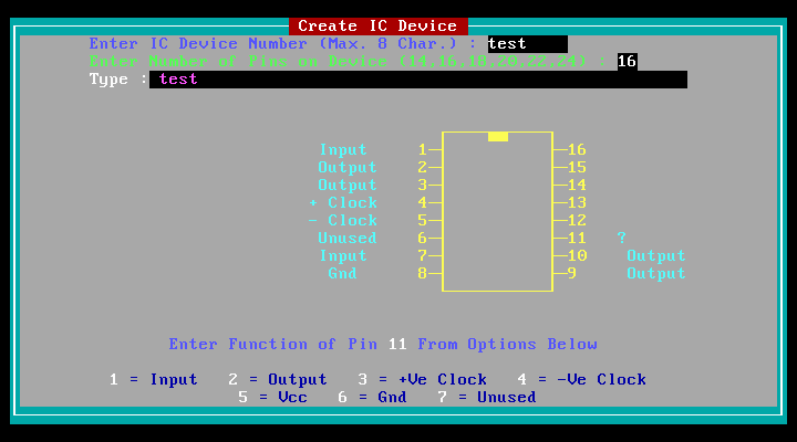
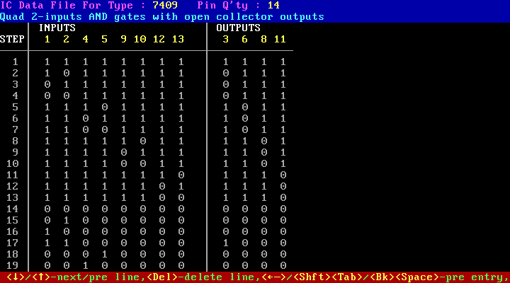
The test library editor is easily used after a bit of familiarisation. It is simple to exit the editor and perform a test, then either return to editing or save the new test to file. Loaded test files can just as easily be modified as well. Test files are, however, appended with a copyright notice for the project's authors, which hardly applies to a user-created file.
I run the software with MSDOS 7 (the DOS that came with Windows 98). I have not tried running it in a Windows DOS prompt, or with any of the other DOS Operating Systems such as FreeDOS.
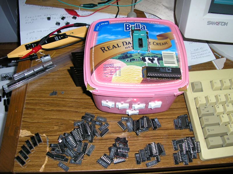
As you can see, the case is opportunistically based around an old ice cream tub where the circuit board happened to sit comfortably on the ledge left for the lid. The lid doesn't quite snap down due to the ICs pressing against it, but it sits comfortably in it's origianl slots, protecting it against being easily knocked off during use. After installing a socket for the 8255 IC, a hole had to be cut to allow it to stick through, eventually I shaped a little cap made from brass that was hot glued to the lid to cover the chip. Plugs and switches were installed in the usual way and the volage regulator attached to the side with small nuts and bolts. In case you decide to dismiss silly notions of aesthetics and go for a similar case design, ensure that the heatsink is suitably rated that it will not get hot enough to melt the light-duty plastic. The heatsink used was specified for 6° C/W, and becomes just warm to the touch during use.
These are the few files that I've written for testing ICs not in the provided library. In some cases they are based on the test routines in the IC library for the Circuit Cellar IC tester, which has support for a vastly superior number of logic chips. I hope eventually to write a program to convert these libraries automatically, as I find doing the job manually very tedious and error prone.
The files should be placed in the "LIB" directory within the directory where the DSA IC Tester software is located.
If anyone has some test files that they've created themselves, I would be very glad to host them here for download with full attribution.
The test library downloadable from the project's webpage includes a file for the 4001. I can't remember the details, but it seems I determined that it didn't work and created this one instead. I think the original 4001 test might have actually been a duplicate of a test for another IC, but I'm not sure which was the other IC.
The ability of the IC tester software to toggle clock pins a specified number of times allows this counter to be tested over its full output range (16,383 clock pulses).
The original provided test for this chip is actually the same as for the 74126, as such it doesn't take into account the inverted Enable input that differentiates the 74125 and the test will always fail.
Tests the popular NE555 LM555 etc. timer ICs. The 555 is an analogue IC, so this digital tester can't fully test the performance of the chip, though it can detect major failures that cause it to misbehave even at logic levels. The test should also work with the 7555 CMOS variant.
As the tester software doesn't allow for 8 pin ICs, the 555 is configured as a 14 pin IC with the upper six pins ignored in the test.
This is pushing the functionality of the tester a bit. The MC789 is a RTL (Resistor Transistor Logic) IC. RTL preceeded the later TTL and CMOS logic families that the tester was designed for. It is designed to run on 3.6V, but I have found a configuration that can be used in the test socket where this particular model of RTL IC can be tested safely.
To connect the IC for testing, insert a 100R resistor into the socket between the GND pin (pin 4) of the MC789 and pin one of the IC socket (top left pin socket). Don't connect the chip with Vcc. With the USER power turned on, the IC's positive supply will be from the tester's pull-up resistors and the 100R resistor to ground prevents the input signals from the tester being pulled low by the low impedance of the ICs inputs. The resistors also keep the currents to the IC within safe levels even though the voltage is higher than the usual 3.6V for MC700 series RTL logic.
I've tested over twenty MC789 ICs this way and it worked fine. However the specific characteristics and internal circuit design of other RTL ICs should be considered before attempting to use a similar method to test other chips in the family.