Inside the bird's nest, oh sorry, Chatterbox. Wires pulled from a large cable were used as bus bars for connecting with the six microphones. The series doides can be seen soldered onto the "COMMON" bus.
Computer Nerd Kev |
Home|About|Projects|Links |
Projects > Chatterbox |
'Chatterbox' 2-Way Radio Simulator |
This device was built to aid in training excercises with the local fire brigade. As part of a "table-top" excercise, designed to help practice fireground management, a tool to take the place of the radios fitted to real firefighting vehicles was required. After pretend microphones proved too easily forgotten about, it was suggested that I build a device to attach to cheaply available replacement radio handsets, which would amplify the signal of any microphone with the press-to-talk button pressed to sound like a real radio transmission.
Inside the bird's nest, oh sorry, Chatterbox. Wires pulled from a large cable were used as bus bars for connecting with the six microphones. The series doides can be seen soldered onto the "COMMON" bus.
The final device allows six handsets to be connected, but this can be expanded to any number required. The wiring of the handsets is exploited so that the microphone circuit in each handset is only connected when its push-to-talk button is pressed, and this signal is amplified so that it can be fed to external PC speakers. As an additional feature, another circuit detects the pressing of the push-to-talk button and plays a short "beep" from the speaker built in to the handset on which the button was pressed.
Rough schematic of the Chatterbox circuit, and the radio handsets used. C8 = 330uF.
A standard electret microphone amplifier circuit using half of an LM358 dual Op-Amp IC was connected to the microphones in all of the connected radio handsets. To allow only the microphone in the handset where the push-to-talk button has been pressed to be used, the ground connection is made to the "button" signal wire of the handsets instead of the Ground wire. This means that the common Ground inside the handsets can only be connected when the push-to-talk button is pressed, therefore the microphone circuit is only completed in the handset where the button is held down and its signal is thereby amplified by the Op-Amp.
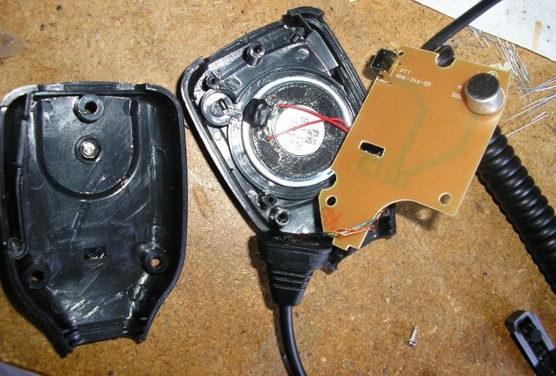
An example of the cheap Chinese microphones purchased from Ebay for use with the Chatterbox, one of which proved to be faulty (of course, it was the one I first tried to test the circuit with). They're no Kenwoods (in spite of what their label may claim), but they'll do for this.
The remainder of the circuit is an optional addition to use to the speakers built in to the handsets in order to make a "beep" sound when the press-to-talk button is pressed, similar to how many real radios make a sound to signal to the operator that they have begun transmitting. Because the Ground connection to the speakers is only active when their push-to-talk button is pressed, only the speaker in the active handset makes the beep, which may prevent accidental pressing/holding of the button (although the sound is picked up by the microphone and therefore plays over the main speakers as well).
Detection of the push-to-talk button being pressed in spite of it's direct connection to Ground, is acheived by detecting the High-to-Low transition of the handset's internal Ground connections. This is done by C1 in combination with IC1b. When the one of the handset's common Ground is activated by the push-to-talk button, this causes C1 to pull the Inverting input of IC1b Low, and holds it below the voltage threshold set by a voltage divider made with R1 and R2 for a time determined by the value of R3 multiplied by C1.
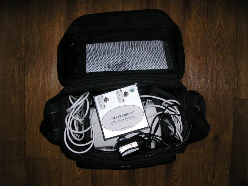
A camera bag just managed to contain the Chatterbox and all its accessories, including a pair of old PC speakers to connect to it.
While the voltage at the inverting input of IC1b is below the reference voltage at its non-inverting input, the output from the Op-Amp is High. This controls the Reset input of the 555 timer IC (IC2), When it is High, the oscillator is enabled. The 555 is in astable configuration, designed to generate an appoximately 800Hz square wave, which is fed to the handset speakers via C6, D1, R6, and volume control VR1 (this ended up set for maximum volume, but it may depend on the performance of the speakers as to whether it can be too loud). D1 is to prevent C6 acting as a Ground connection to the handset microphones via the low resistance of the speaker coil, I used a schottky type to minimise voltage drop and therefore allow maximum volume, but a regular silicon diode might also work.


This Veroboard layout was created in VeroDes. Design file,
bottom side view.
Note that C8 is not shown, it was mounted off-board in my build.
In use it was found that when a push-to-talk button was pressed shortly (less than a second or two) after the release of another, a beep wouldn't be made. While so far I haven't attempted to fix this issue, a lower value of R3 might solve the problem.

Set up with magnetic grid boards for the table-top training excercise.